


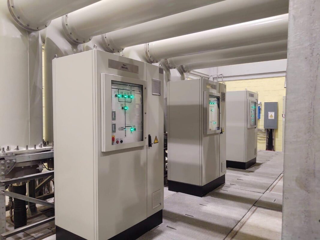
A local control cabinet (LCC) or Local Control Panel (LCP) is usually provided for each circuit breaker position (Please see photo 1).
The control and power wires for all the operating mechanisms, auxiliary switches, alarms, heaters, CTs, and VTs are brought from the GIS equipment modules to the LCC using shielded multiconductor control cables. In addition to providing terminals for all the GIS wiring,
Although the LCC is an extra expense, with no equivalent in the typical AIS, it is so well established and popular that elimination to reduce costs has been rare. The LCC does hire the advantage of providing a very clear division of responsibility between the GIS manufacturer and user in terms of scope of equipment supply.
Each circuit breaker of the gas insulated substation (GIS) is provided with a control cabinet for local control and monitoring of the respective bay and is generally placed in front or adjacent to their GIS bays depending on the voltage level.
The control cabinet is metal enclosed, free standing, made of sheet steel, and provided with a
lockable hinged door and door operated lights. The local control cabinet has all necessary control switches, local/off/remote lockable selector switches, close and open switches, measuring instruments, all position indicators for circuit breakers, disconnect switches and grounding switches, alarms, mimic diagram, AC and DC supply terminals, control and auxiliary relays, and so on.
Also for making operations practicable and convenient as well as trouble-free wiring from Gas Insulated Switchgear (GIS) to the substation control room, a LCC is provided. Even though LCC increases the cost when compared with air-insulated switchgear, it is so well liked attempts to get rid of LCC to trim down cost have not succeeded. The LCC does have the benefit of providing a very clear division of liability between the GIS manufacturer and user in terms of scope of equipment supply. The problem had appeared while testing the LCC during the factory acceptance test (FAT).
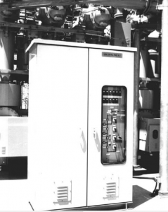
Photo 1: GIS Local Control Cabinet
Local Control Cabinet issues:
Switching and circuit breaker operation in a GIS produces internal surge voltages with a very fast rise time of the order of nanoseconds and peak voltage level of about 2 per unit These “very fast transient” voltages are not a problem inside the GIS because the duration of this type of surge voltage is very short-much shorter than the lightning impulse voltage. However, a portion of the very fast transient voltages will emerge from the inside of the GIS at any places where there is a discontinuity of the metal enclosure-for example at insulating enclosure joints for external CTs or at the SF6-to-air bushings. The resulting “transient ground rise voltage” on the outside of the enclosure may cause some small sparks across the insulating enclosure joint or to adjacent grounded parts-these may alarm nearby personnel but are not harmful to a person because the energy content is very low. However, if these very fast transient voltages enter the control wires, they could cause misoperation of control devices. Solid-state controls can be particularly affected. The solution is thorough shielding and grounding of the control wires. For this reason, in a GIS the control cable shield should be grounded at both the equipment and the LCC ends using either coaxial ground bushings or short connections to the cabinet walls at the location where the control cable first enters the cabinet.
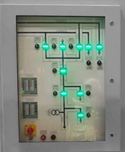
Example of Local Control Cabinet mimic diagram and alarms:
The LCC has a mimic diagram of the part of the GIS being controlled. Associated with the mimic diagram are control switches and position indicators for the circuit breaker and switches. Annunciation of alarms is also usually provided in the LCC. Electrical interlocking and some other control functions can be conveniently implemented in the LCC.
This is an example of mimic diagram show at photo 2:
a. A mimic diagram showing the arrangement of electrical equipment in the bay including bus
bar isolating links.
b. Control switches and local/off/remote changeover (lockable) for operation of all circuit
breakers, disconnect switches, and grounding switches.
c. Position indicators showing the position of all circuit breakers, disconnect switches and
grounding switches.
d. Overriding interlock switch between disconnects and grounding switches associated with
circuit breakers (depending on the user’s requirements).
e. SF6 gas zones.
f. The color of the mimic bus should be according to the user’s requirements.
The following minimum alarm is provided as a local alarm in the LCC:
- SF6 gas pressure Low–Low, Stage 1 alarm for each gas zone/section (in the case of a single phase, an alarm is provided for each phase)
- SF6 gas pressure Low–Low, Stage 2 alarm for each gas zone/section (in case of a single phase, the alarm is grouped for all phases)
- Excess run time of the motor for the circuit breaker, disconnecting switch, and ground switch
- Spring overcharged for the circuit breaker mechanism
- Loss of DC for the trip and close circuit
- Circuit breaker trip
- VT supply fail (VT MCB trip)
- Loss of AC supply
- Circuit breaker mechanism failure
- Local/remote switch
- Pole discrepancy operated (for single-phase breaker)
- Trip circuit failure
- Loss of DC supply to circuit breaker motor.
All CT secondary taps should be wired to the local control cabinet. The CT terminal block is
such that it will provide isolation and testing facilities of CT secondaries at the cabinet. For multi ratio CTs the terminal block is provided on the LCC as per IEEE C57.13 to facilitate connection of various taps. Facility is provided in the LCC for shorting and grounding of secondary terminals.
Potential transformer (PT) secondary windings are terminated at the local control cabinet through a terminal box. For PT wiring in the LCC, each phase of each circuit is provided with a miniature knife switch and a high rupturing capacity (HRC) fuse/supervised mini circuit breaker (MCB). Knife switches are located on the PT side of fuses. Separate terminals are provided for PT fuse supervision.
Interlocks are followed by LCC:
The following interlocking scheme is incorporated inside the cabinet for reasons of safety and convenience of operation, and also to prevent incorrect switching sequences that could lead to a hazardous situation to plant, equipment, or personnel. The electrical interlocking is effective under both local and remote operations. The following are some typical requirements for interlocking:
- Manual operation of the disconnect and grounding switches is only possible under electrical interlock release conditions. A key switch for overriding interlocks between disconnect and grounding switches associated with circuit breakers during maintenance is provided in the control cabinet.
- Mechanical and electrical interlock between disconnect and grounding switch operation is provided.
- The electrical interlock scheme is fail-safe to prevent loss of interlock function upon loss of control voltage.
- Electrical interlock between the line PT secondary voltage and respective high speed grounding switch operation is provided through under voltage relay contacts.
- The feeder grounding switch is interlocked with the corresponding circuit breaker and disconnect switch.
- The bus bar grounding switch is interlocked with all disconnect switches on the same busbar section.
- The high speed grounding (fast-acting grounding) switch is interlocked with the associated circuit breaker open.
Also this interlocking requirement must be see in LCC:
No closing of dis-connectors with the earthing switch closed.
No closing of dis-connector when a load is connected.
No switching of the earthing switch when the bus bar or equipment is energized.
No opening of dis-connector under load.
No closing of circuit breakers if the associated disconnectors are in an intermediate state.
CB can be connected only one bus at a time.
No paralleling of buses by dis-connectors when bus coupler is open.
Only local mode operation for CB when dis-connectors are open.
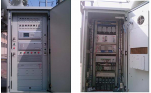
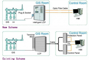
New Intelligent Local Control Cabinet:
At the present stage, using a combination of existing mature secondary technology and traditional switching equipment, to enhance the level of intelligence, is a realistic scheme to achieve switchgear intelligence.
At present, the intelligent control devices have been developed for GIS monitoring. Protection and intelligent control panel based on the intelligent control devices have also been designed.
Integrating GIS control function and the secondary functions such as measurement and control function, intelligent control devices can realize the data acquisition and analysis, remote and local control, event recording, online monitoring, interlocking functions etc. Intelligent control devices simple and replace the relays, contactors, special measuring instruments, alarm light plates in the traditional GIS LCC, which make it possible to achieve a combination between primary and secondary equipment, an integration of measurement and control, operation and GIS intelligent control.
The GIS intelligent device samples and processes the bay current and voltage signal, calculate the current, voltage, power, power factor and the measurements of fundamental frequently and 3rd to 15th odd harmonics components, displays them on the local MMI (Man-Machine Interface) and sends them to the station level system via Etheret.
Therefore, the control and signal cables have been reduced greatly. The device achieves inner-bay interlocking, phase discrepancy trip and synchronism checking by software. The traditional relay connection circuits have been cancelled. By sampling the signals from sensors, auxiliary contactors and the status signals of GIS, the device can monitor GIS status including position and SF6 density, and forecast the remaining life of GIS. The programmed operation server is embedded in the intelligent device.
Therefore, the primary equipment program operations of GIS can be realized through the inner operation sheet, which has high reliability, fast response, and the operation records can be traced back.
Together with the bay protection devices, the GIS intelligent device can be installed on the same panel-GIS intelligent LCC, next to the GIS. Through optimizing control connection circuits, the integration of protection, monitoring and control, intelligent control of GIS for a bay can be realized.
The protection device samples the bay current and voltage and implements the protection algorithm. The outputs of protection trip connect to the operating circuit by the interal wiring. For those protections which need information from other bays, such as transformer protection and busbar protection, a decentralized scheme will be suggested.
The electric interlocking mode among GIS components can be selected through the switch on the LCC, which can be switched feely form software interlocking, hardware interlocking, putting into interlocking to lifting interlocking. The GIS intelligent control device samples the status signals of all the isolators in the bay, the status signals of other bays are transmitted via the digital
communication interface via optic-fiber cable, so the interlocking based on software and communications can be easily implemented.
The GIS intelligent LCC connects to GIS via standardized plugs and sockets, and communicates with the station level system in control room via optic-fiber cables, which forms the basic structure of the digital substation based on the protection and Intelligent LCC.
Figure 1 show shows the technical ideas of the GIS intelligent LCC and photo 3 show an intelligent installed in a substation in china country.
Testing of Local Control Cabinet:
During Factory Acceptance Test (FAT), all the operations and logics from LCC are checked by Customer.
Because of that FAT for control panel is become difficult. Looping method is used for testing. Looping can be done only by studying drawings. For single annunciation checking, number of wirings is needed. This increases complexity as well as some annunciations or function cannot be performed during Factory Acceptance Test.
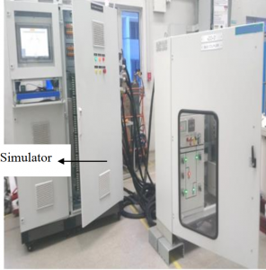
Now all test for LCC done by simulation kits.
With this simulation kit, fully functional assessment of LCC panel can be conducted viz panel wiring; interlock wiring, component functioning etc. This way any abnormalities in LCC will be detected in the factory itself resulting in reduced site complains.
With simple plug in harting connection there is no longer need for complex wiring and tiresome setup arrangements for LCC testing. So, considerable amount of man hour is saved in this Process.
This article relates to the article posted at switchgearcontent.com